
1. Servo-Pump
The basic settings I have tried. Servo-Pump 1 has the Kp 0.99 and the Tn 0.010, exactly the same pump values were used for the pump. Let the pumps run more smoothly. It is also important that the pump runs smoothly.
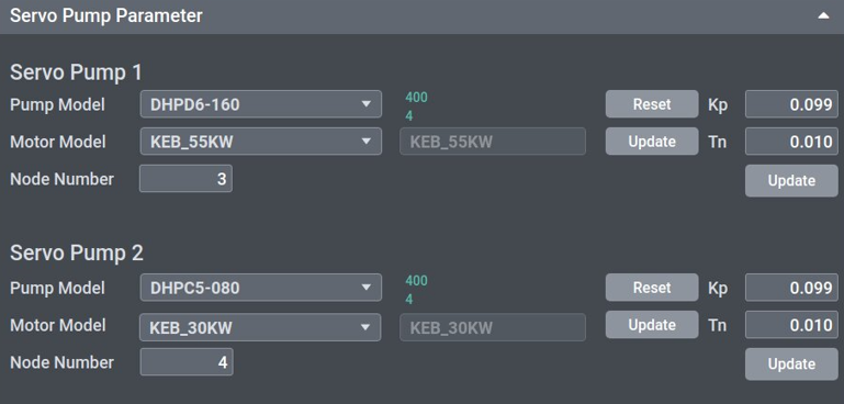
1.1 Basic parameter for servo pump and Standstill parameter of pressure
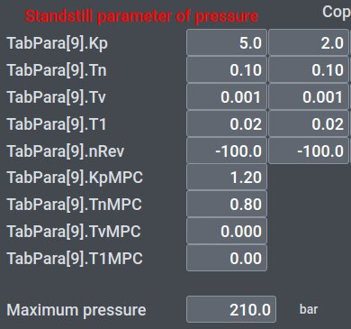
We only decreased from TabPara[9].KpMPC 1.50 to 1.20 and TabPara[9].TnMPC from 0.5 to 0.8. You can check the parameters in the photo below.
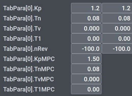
Additionally, I changed the basic parameter for the servo pump: TabPara[0].TnMPC 0.08. You can check the parameters in the photo below.
2. Settings on the injection side
Two relevant points stood out to me during my attempts on the DL650A5. On the one hand, I had to make adjustments to the servo pump parameter settings, particularly changing the nRev value. At the beginning, nRev was -500, after the adjustments it was -200. The Kp-value was increased from 20 to 30.
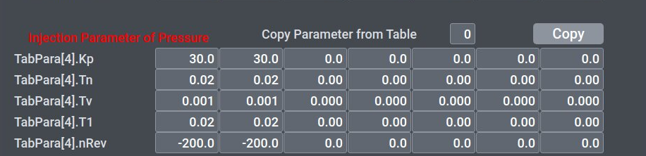
It was also important to adjust the linearization of the injection speed. In my experiments, the injection speed could be improved from -118 mm/s at 2000 rpm (100%) to -109 mm/s.
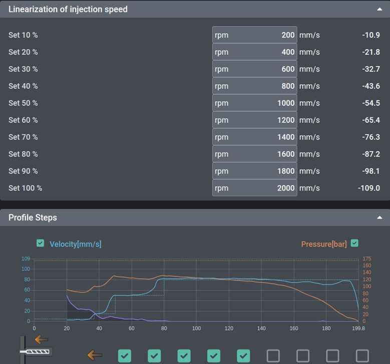
OPEN LOOP-Mode
2.1 Holding Pressure
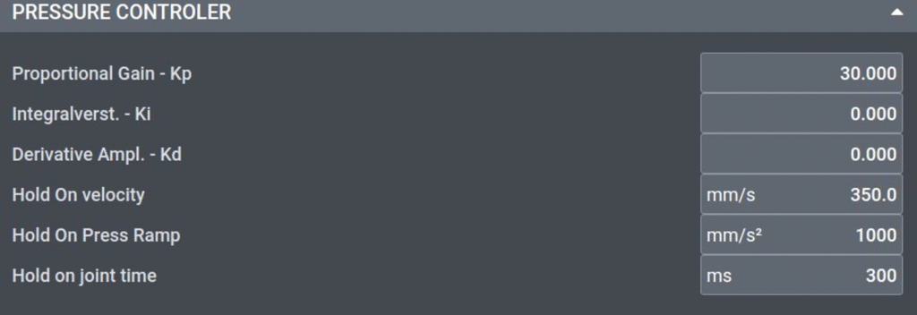
Even the reprint had to be adapted accordingly. The pressure controller Kp was set to 30, a critical value for the stability of the post-pressure profile. Additionally, I optimized the following parameters:
Hold-On Velocity: 350 mm/s
Hold-On Press Ramp: 1000 mm/s²
Hold-On Joint Time: 300 ms
These values were determined through targeted adjustments and led to more stable and controllable re-printing behavior.
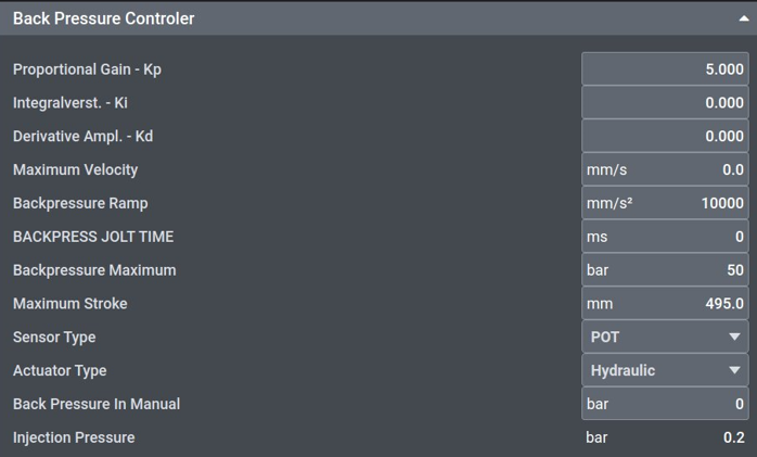
2.2 Back Pressure
The most important parameters are in the back-pressure controller. The Kp value should be 5; the other values, such as Ki and Kd, have shown no influence in my current experiments. A backpressure ramp of 10000 mm/s².
3. Clamp Side
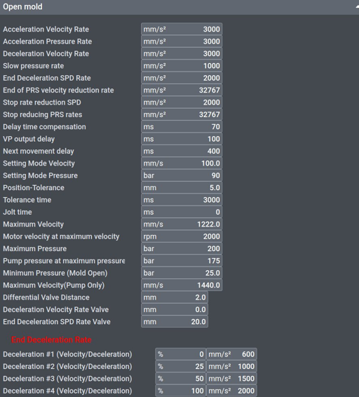
First, I adjusted the individual parameters step by step and focused on Mold Open. I reduced the position of the form opening from 80 mm to 2 mm using the Differential Valve Distance value. This produced the greatest output in my experiments. The acceleration speed and acceleration pressure rate also have an effect, but only when the values are greatly reduced or set to 0. I could not detect any other values in my tests on the Austrian DL650A5.
3.1 Ejector
The ejector and its travel profile can best be adjusted through two times: the delay time compensation and the jolt time. The jolt time is set to 1 ms, otherwise the ejector will not follow a defined profile, but will move at nearly the set maximum speed.
When the Delay Time Compensation is set to 140 ms and the Jolt Time is set to 1 ms in both directions (forward and backward), my experiments show a clean travel profile – and, more importantly, more accurate positioning for potential robot removal. It is also important to adjust the ejector’s RPM number, as this also affects the accuracy.
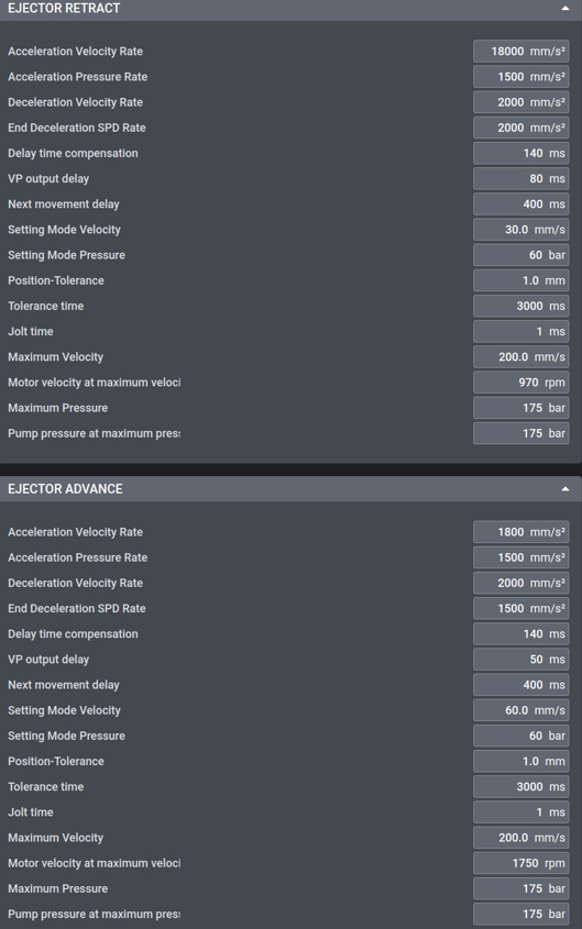
The values were taken from tests on an Austrian DL650A5 and may not be directly applicable to every machine of this type. I cannot guarantee that they will work universally, as further adjustments may be necessary depending on the specific DL650A5 unit or setup.