
Date: July 14, 2025
작가: Woojin Control Team
Target: Engineers performing on-site setup and commissioning of KEBA D3 drives
🧠 0. Save Parameter Changes to ROM
- Command: PARA_SetCmd.Save (2014[1]h)
- How to Save:
Set the value to 1 to store current drive parameters in ROM.
In DriveManager: Click on the IC chip icon.


| PARA_SetCmd.Save | 2014[1]h | To save, set this to 1 |
🔌 1. Voltage Supply Parameters
DriveManager Tab: Supply

1-1) DC Supply Voltage Settings
| Parameter Name | Address |
| Actual DC Voltage | 225A[1]h |
| Voltage Supply Select | 225A[2]h |
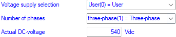
| Actual DC-voltage | 225A[1]h |
| Voltage supply selection | 225A[2]h |
1-2) Braking Resistor Settings

| Rated resistor | 22C8[1]h |
| Continuous power | 22C8[2]h |
| Peak power for 1 second | 22C8[3]h |
| Parameter Name | Address |
| Rated Resistor | 22C8[1]h |
| Continuous Power | 22C8[2]h |
| Peak Power (1 sec) | 22C8[3]h |
💡 Consider increasing brake resistor capacity depending on motor/load type.
🛰 2. Node ID Configuration
DriveManager Tabs:
- PowerLink
- Others → CANOpen
| Parameter Name | Address | Note |
| SWNodeID_U8 | 1F93[3]h | Set desired node ID |
| EPL_NodeIDAutoIncrement | 25C9[0]h | Default: ON → Turn OFF for manual setting |
| | |
| | |
| SWNodeID_U8 | 1F93[3]h | |
| EPL_NodeIDAutoIncrement | 25C9[0]h | *Note : Default ON; To change Node ID manually, please set OFF this parameter |
🔄 3. Motor Rotation Direction
DriveManager Tab:
Motion Profile → Standardization/Units
| Setting | Bit No. | FALSE (default) | TRUE |
| Polarity – Position | 6 | Clockwise | Anti-clockwise |
| Polarity – Speed | 7 | Clockwise | Anti-clockwise |
🧾 In Woojin systems, extrusion = anti-clockwise, others = clockwise.
| | |


| Polarity – Position | Bit 6 | FALSE : clockwise (Normal) TRUE : anti-clockwise (Reversed) |
| Polarity – Speed | Bit 7 | FALSE : clockwise (Normal) TRUE : anti-clockwise (Reversed) |
📐 4. Speed Controller Gains (Kp & Tn)
DriveManager Tab: Control → Basic Settings
→ Auto-calculated after running Automatic Inertia Detection
| Parameter Name | Address |
| Kp (Proportional) | 2B87[1]h |
| Tn (Integration) | 2B87[2]h |
| | | |

| CON_SCON_Ctrl.Kp | 2B87[1]h |
| CON_SCON_Ctrl.Tn | 2B87[2]h |
⚙️ 5. Encoder Offset & Inertia Tuning
5-1) Automatic Tuning
| Function | Address | Value |
| Encoder Offset Detect | 2BFC[1]h | 13 |
| Inertia Detection | 2BFC[1]h | 10 |
| Axis 2 SDO Address | 33FC[1]h |
| | |

⚠️ Caution
- Must be in “Ready to switch on” state
- Ensure proper wiring, position, and safety before executing
- Motor will oscillate during Inertia Detection
5-2) Control Stiffness
| | |
Step-by-step Guide:
- Modify Stiffness
2BF3[2]h → Set custom stiffness value - Recalculate Gains
2BFC[1]h = 12 (CALC_SCON) - Verify Results
- 2B87[1]h (Kp)
- 2B87[2]h (Tn)
📝 Summary
| Category | Key Action |
| Save Config | PARA_SetCmd.Save = 1 |
| Supply Voltage | Confirm 225A settings |
| Node ID | Manually set if needed |
| Rotation Direction | Match axis-specific convention |
| Gain Tuning | Use Auto Inertia detection |
| Encoder/Stiffness | Ensure mechanical/electrical safety |