


Signal Overview – Description of the Mold Closing and Tonnage Build-Up Process
The graphic provides a combined view of the most relevant signals during the mold-closing sequence.
The x-axis shows the crosshead position, making it easy to correlate the clamp mechanics with the electrical and control signals.
- Purple: Actual drive torque [% of maximum]
- Gray: Internal control step (CtrStep = 28 for Mold Closing, 36 for Tonnage Build-Up)
- Orange: Platen position [mm]
- Red: Mold lock force measured via tie bar tension sensor [kN]
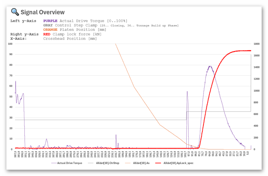
Phase 1: Mold Closing Phase – Control Step 28
During the Mold Closing phase (CtrStep = 28):
- The platen (orange) moves quickly toward the fixed mold half as the toggle operates in the high-speed, low-force region. The clamp unit is driven to the target position SsML (“Mold Zero Tonnage Position”). Depending on the selected clamping force and the machine size, SsML is typically between 1 mm and 10 mm (e.g. up to 10 mm on a TE650).
- The mold lock force (red) remains close to zero throughout this phase, as expected.
- The drive torque (purple) shows several small peaks due to
- friction variations,
- inertia compensation,
- dynamic toggle movement.
If the torque increases abnormally (e.g., sprue or insert remains between the plates), the machine can stop immediately.
This is the only phase where drive torque is a valid monitoring quantity.
Phase 2: Tonnage Build-Up – Control Step 36
When the clamp transitions into the Tonnage Build-Up phase (CtrStep = 36):
- The drive torque rises sharply, not because of mold resistance, but because the motor must accelerate and push the toggle into the force-amplification zone.
This acceleration requires more than 50% of the motor’s maximum torque, even though mold resistance is still very low.
- As the crosshead reaches approx. 80 mm, the mold lock force (red) begins to rise steeply and smoothly up to the configured maximum value (e.g., 1700 kN).
- During this force-rise, the drive torque reaches approx. 80% of the maximum torque, which is the required torque to achieve full clamping force with the toggle mechanism.
During the Clamp Closing phase the crosshead performs a purely linear motion. This linear movement is converted by the toggle mechanism first into a high-speed approach of the moving platen and, in the final part of the stroke, into a force-intensive motion for mold compression.
For the TE170A5 machine, this behavior can be seen in the attached diagram:
- At a crosshead position of approx. 80 mm, the moving platen is at approx. 3 mm.
- From this point onwards the mold lock force starts to build up rapidly.
- The mold lock force is measured using a tie bar tension sensor mounted on one of the tie bars.
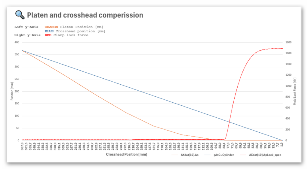
The graphic illustrates the relationship between crosshead motion, platen compression, and mold lock force during the clamp closing sequence of a toggle system. The three curves show how the mechanical behavior transitions from a speed-dominated phase into a force-dominated phase.
As described earlier, SsML is the final point of the mold-closing profile, where the mold halves are in contact but no clamping force is generated yet.
If the SsML position is configured incorrectly, the following issues may occur:
SsML set too small
If SsML is defined too close to the mechanical end position, clamping force begins to build up already during the last phase of the Mold Closing step.
- In this phase, force should normally remain as low as possible to avoid damaging the mold.
- A too-small SsML position may also cause the system to detect premature resistance, leading to activation of the mold protection function, e.g., due to inserts, sprue, or misalignment.
SsML set too large
If SsML is configured too far away from the actual mold-touch point, the system switches too early into the Tonnage Build-Up step.
- At this moment, the mold protection functionality is no longer active, since the machine assumes that the mold is already fully closed.
- This creates a significant risk of mold damage, especially if foreign objects or misaligned inserts are present.
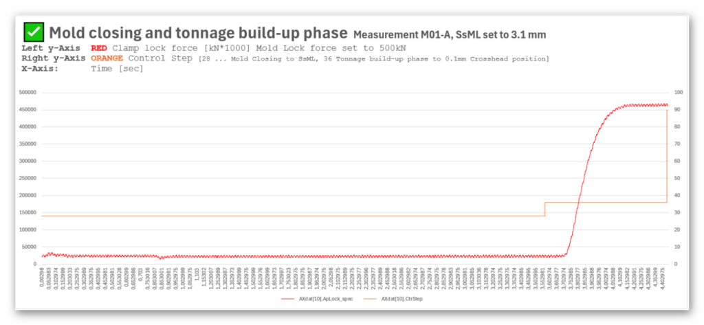
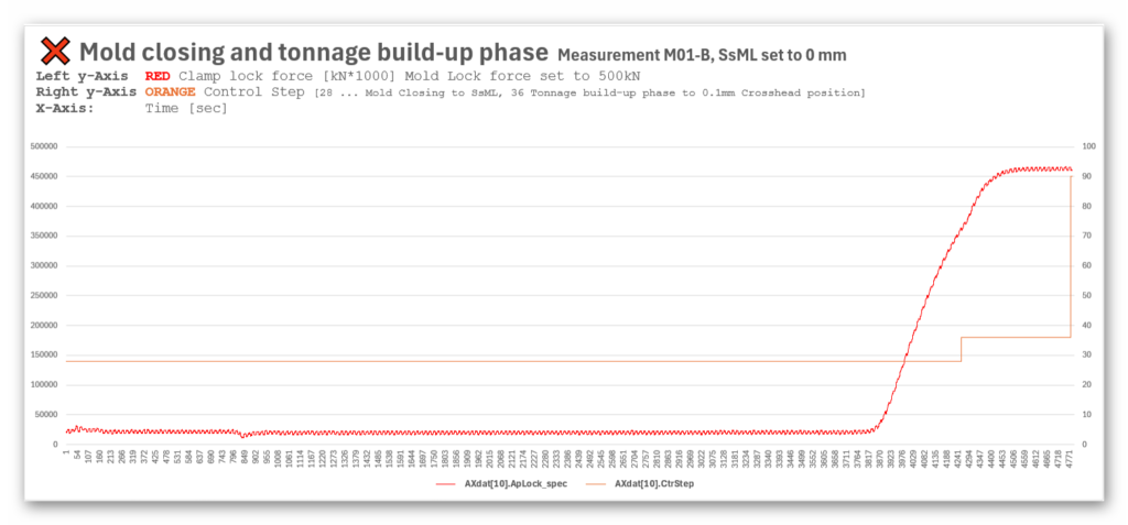
The next diagrams show the complete Mold Closing phase (internal control step 28) followed by the Tonnage Build-Up phase (control step 36).
- The orange curve represents the internal control step number, indicating which phase of the clamp process is currently active.
- The red curve shows the measured mold lock force, detected via the tie bar strain gauge.
The two measurements demonstrate the difference between a correctly set SsML position and an incorrect SsML setting, and how this affects the moment when the mold lock force begins to rise.
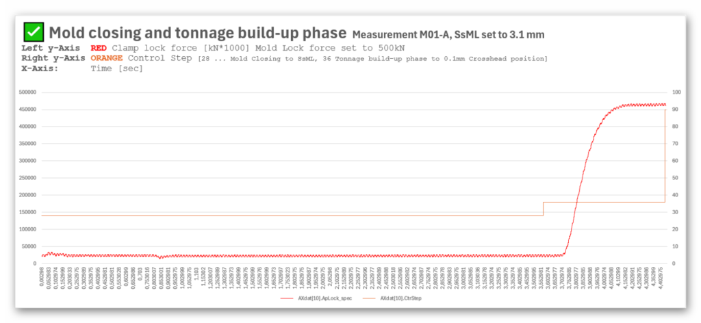
SsML position is configured correctly (3.1 mm for a target clamping force of 500 kN).
- During the entire Mold Closing step (orange = 28), the red force curve remains close to zero, meaning no tonnage is generated prematurely.
- When the process transitions to the Tonnage Build-Up step (orange = 36), the force rises immediately and steeply, exactly as intended.
- This confirms that the SsML position is correct: the system switches from closing to force generation only after the mold halves are in full contact.
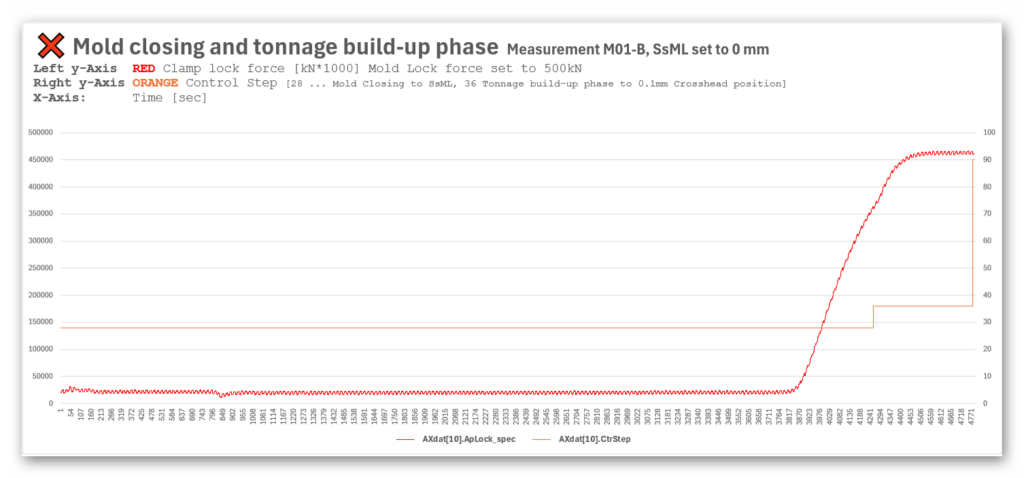
SsML is incorrectly set to 0 mm,
- The force increase begins while control step is still 28, i.e., during the Mold Closing phase.
- This is undesirable because mold protection is still required during this step.
- Force buildup during control step 28 indicates that the machine transitions into a force-dominant region before the intended SsML position, increasing the risk of mold damage.
Therefore, the SsML position should not be user-adjustable. Instead, it must be determined automatically during the automatic mold-height adjustment process. This ensures that the zero-tonnage position is always set correctly, prevents premature force build-up during mold closing, and significantly reduces the risk of mold damage.
If a foreign object is trapped inside the mold during the closing process, the mold lock force can rise far above the configured clamping force. Without an active monitoring function during the Tonnage Build-Up phase, the system will continue increasing force until the mechanical stop is reached or drive power will reach limitation. This can lead to severe mold damage.
To demonstrate this issue, we inserted coins into the mold to simulate foreign material. A customer had previously performed a similar test and reported that the machine exceeded the set clamping force by a factor of two, due to missing monitoring during the Tonnage Build-Up phase.
To address this, we implemented an envelope monitoring function based on the actual torque and a reference curve recorded at 500 kN.
With the coin installed, the envelope monitoring was configured to abort Tonnage Build-Up immediately once the measured mold lock force exceeded 10% above the set value (550 kN). This ensured that no damage occurred to the mold.
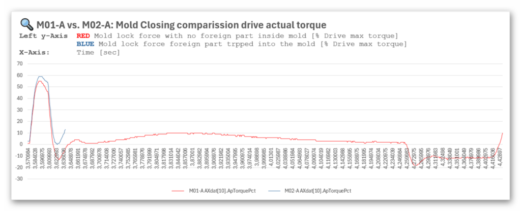
The first graphic compares the drive actual torque during a normal closing cycle (red) to a closing cycle with a coin trapped inside the mold (blue). Even though a foreign object is present, no significant difference in the torque traces can be observed during the Tonnage Build-Up phase. This is because the torque increase is mainly caused by acceleration at beginning of tonnage build-up phase. Therefore, actual torque is not a suitable indicator for detecting foreign material during Tonnage Build-Up.
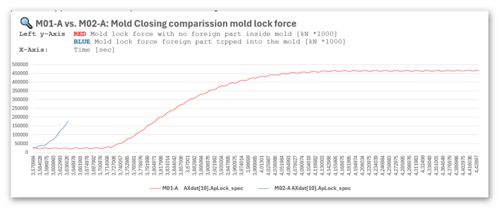
The second graphic shows the mold lock force over time.
- In the normal cycle (red), the force buildup occurs at the expected point in the process.
- With the coin installed (blue), the force begins to rise much earlier, indicating resistance before the intended dead-center region.
The early force rise triggers the envelope monitoring, leading to an immediate abort of the Tonnage Build-Up phase at approx. 550 kN to prevent mold damage.
The third graphic shows the mold lock force plotted over the crosshead position instead of time.
This representation clearly highlights the mechanical effect of the foreign material:
- Normal closing (red):
Force buildup starts at around 80 mm crosshead position. - Closing with coin in mold (blue):
A noticeable force increase occurs already at approx. 87 mm, significantly earlier than in the normal cycle.
Since the crosshead position correlates directly with the toggle angle, this early deviation is a clear indicator that something prevents the mold from fully closing.
The monitoring system reacts and aborts Tonnage Build-Up to avoid damage.
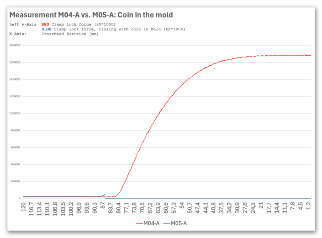
Mold lock force vs. crosshead position with and without foreign object. The foreign material causes an earlier force increase (87 mm vs. 80 mm), enabling early detection and safe abort of Tonnage Build-Up. A foreign object is trapped inside the mold, causing a large overshoot in mold lock force.
If the increase in clamp lock force is monitored during operation, foreign material inside the mold can be detected very easily by observing deviations in the force-increase point relative to the crosshead position.
During the mold-height adjustment process – or during manual mold-height setup – the reference force-rise position must be recorded once for the current mold.
All subsequent closing cycles can then be monitored with high precision during the Tonnage Build-Up phase.
This enables early detection of abnormal resistance and prevents clamping force overshoot, ensuring that mold damage is avoided.
During the first step of the mold-height adjustment process, the clamp unit is closed in order to measure the actual mold lock force. If the mold height is set too high, it may occur that the configured clamping force is significantly exceeded during this very first closing cycle.
When an overshoot is detected, the system automatically moves the mold backward to reduce the clamping force.
However, any force overshoot must be strictly avoided, even during the first closing movement used for force measurement. Exceeding the maximum allowable mold lock force at this stage can already lead to tool damage.
Therefore, the process must ensure that during the initial closing cycle—before any force measurement or adjustment is made—the system reliably prevents excessive clamping force. This guarantees that the correct mold height can be determined safely without risking mold or machine damage.
When the automatic mold-height adjustment process is started, the system detects the point at which the mold lock force begins to exceed 5% of the target clamping force.
For example, if the force rise begins at a crosshead position of 80 mm, this marks the start of the non-linear force increase.
Based on this detection, the SsML position can be placed a few millimeters before this point (e.g., at 84 mm , add tolerance window of e.g. 5%) -> new fix value.
This ensures that SsML is always calculated correctly and automatically for the current mold setup.
As a result, the customer no longer needs to set SsML manually.
On the clamp-close screen, the numeric input field will be replaced by a numeric output field—SsML becomes a display-only value generated by the machine.
During the Tonnage Build-Up phase, the system continuously monitors the increase in mold lock force.
If the force rises earlier than expected—specifically, if the increase occurs 5% before the reference SsML (tolerance window)— the internal control step immediately aborts the Tonnage Build-Up phase.
This prevents excessive clamping force, protects the mold, and ensures that foreign material or misalignment is detected early.
The mold-height adjustment process must ensure that the very first closing attempt never exceeds the configured maximum clamping force.
The system must regulate the motion so that even during the initial force measurement cycle, the clamping force remains within a safe range.
This guarantees that the correct mold height can be determined without risking damage to the mold or the clamping unit.
The diagrams compare two measurements of the mold-closing and tonnage build-up process.
The x-axis shows the progression over time.
Two parameters are evaluated:
- Mold Lock Force (red), measured via the tie bar tension sensor
- Internal Control Step (orange), represented by AXdat[11].CtrStep
- Control Step 28 = Mold Closing to SsML
- Control Step 36 = Tonnage Build-Up Phase
The key difference between M01-A and M01-B is the SsML setting:
- M01-A: SsML = 3.1 mm (correct setting for 500 kN)
- M01-B: SsML = 0 mm (incorrect setting)
In this measurement, SsML is configured correctly.
- During Control Step 28 (Mold Closing), the mold lock force remains close to zero.
- Only when the process transitions into Control Step 36 does the force begin to rise sharply.
- This behavior is correct: the clamping force is generated only after Mold Closing is completed.
This confirms that SsML = 3.1 mm prevents premature force build-up and ensures that mold protection remains active throughout the closing phase.
In M01-B, SsML is incorrectly set to 0 mm.
- The diagram shows that the mold lock force starts to increase already during Control Step 28.
- At this moment, the machine still assumes that mold protection must be active, because Mold Closing is not yet finished.
- However, due to the incorrect SsML position, force is generated too early, before the transition to Control Step 36.
This results in no monitoring of the tonnage build-up transition and creates a potential hazard:
- Foreign material (e.g., sprue, inserts, misalignment) may not be detected.
- The force can exceed the configured clamping force.
- Mold damage becomes possible.
The comparison clearly demonstrates that:
- A correct SsML value ensures that force build-up starts only during the intended Tonnage Build-Up phase.
- An incorrect SsML value causes a force rise during Mold Closing, when mold protection should still be active.
- Therefore, SsML must be automatically calculated and must not be manually adjustable.
To evaluate how foreign material inside the mold affects the clamp-closing process, measurement M02-A was performed with a coin placed inside the mold.
Both the drive actual torque [%] and the mold lock force (tie bar tension sensor) were recorded and compared against the reference measurement M01-A (normal closing without foreign material).
The objective was to determine whether foreign material can be detected reliably and which signal—torque or mold lock force—provides a meaningful indication during the Tonnage Build-Up phase.
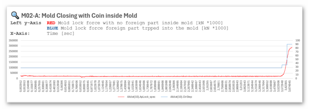
- M02-A: Mold Closing With Coin Inside Mold
This diagram shows:
- Red: Mold lock force during normal closing (M01-A).
- Blue: Mold lock force when a coin is trapped between the mold halves (M02-A).
- In the normal cycle (red), force remains near zero during Mold Closing (CtrStep 28) and rises only in the Tonnage Build-Up phase (CtrStep 36), but much earlier.
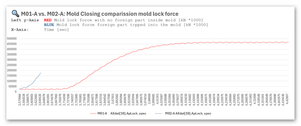
This diagram directly compares the force curves of M01-A and M02-A over time.
- Normal closing (M01-A):
The mold lock force increases smoothly and only after reaching the correct SsML region.
- Closing with coin (M02-A):
The force curve rises significantly earlier and much more steeply due to the trapped object. - This abnormal early force rise is easily distinguishable from normal behavior.
This confirms that the tie bar tension sensor provides a reliable and repeatable signal to detect mold contamination, misalignment, or foreign material.
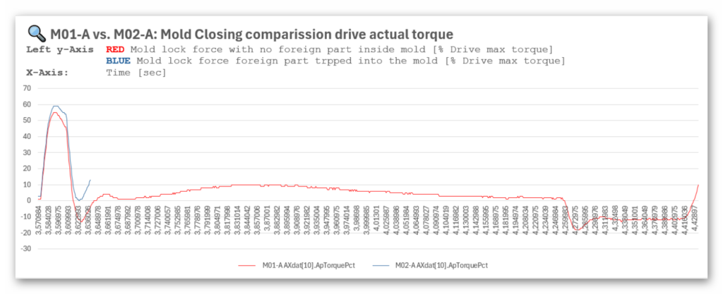
This diagram compares the drive torque [% of motor maximum] for both scenarios.
- The torque curves of M01-A and M02-A show very little difference, even when the coin is trapped in the mold.
- The torque increase is mainly caused by:
- the motor speed ramp
- mechanical inertia
- Because of these factors, drive torque is not sensitive enough to reliably detect foreign material.
This proves that drive torque is not suitable as a monitoring parameter during Tonnage Build-Up.
Measurement M03 compares two clamp-closing cycles at 500 kN clamping force, but with different SsML settings:
- M03-A: SsML = 5 mm
- M03-B: SsML = 3 mm
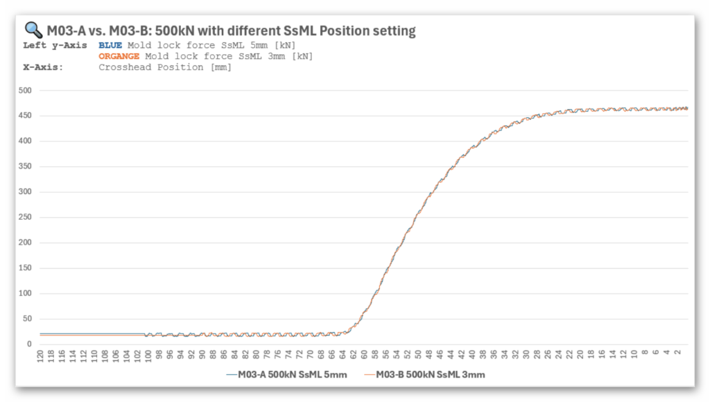
The purpose of this measurement is to verify whether the selected SsML value affects the force-increase characteristics when the mold lock force is evaluated relative to the crosshead position.
The diagram plots:
- Y-axis: Mold lock force (kN) measured via the tie bar tension sensor
- X-axis: Crosshead position (mm)
The force curves of M03-A (5 mm) and M03-B (3 mm) lie almost perfectly on top of each other.
The following observations can be made:
- The force onset occurs at the same crosshead position in both measurements.
The point at which the toggle mechanism enters the force-amplification region is independent of SsML. - The slope and shape of the force build-up curve are identical.
This confirms that the mechanical behavior of the toggle system, in terms of force development, is determined by the geometry and kinematics. - SsML does not shift or influence the physical force rise.
It only defines the logical transition point between Mold Closing and Tonnage Build-Up.
The results clearly confirm the insights gained from M01 and M02:
- The crosshead-based force increase is a stable and reproducible indicator of mold resistance.
- The SsML setting has no influence on where the force increase actually occurs.
- Therefore, monitoring the mold lock force relative to the crosshead position is the correct approach for detecting foreign material and preventing force overshoot.
- SsML should be automatically calculated, not manually set by the customer.
Measurement M04 repeats the experiment from M03, but with the maximum clamping force increased from 500 kN to 1700 kN.
Two closing cycles are compared:
- M04-A: SsML = 5 mm
- M04-B: SsML = 3 mm
The diagram plots the mold lock force (kN) over the crosshead position (mm).
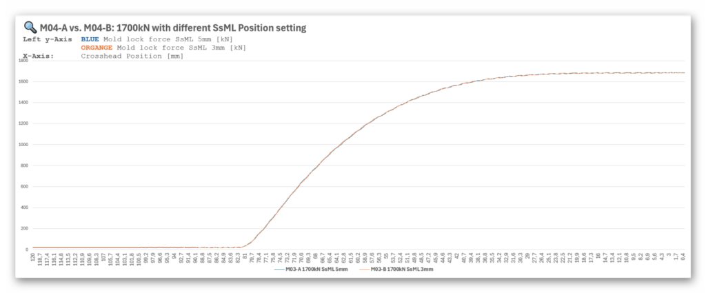
Just as in M03, the goal is to determine whether different SsML settings influence the force-rise characteristics when the mold lock force is evaluated relative to the mechanical crosshead position.
- The force curves of M04-A and M04-B are identical.
Despite different SsML values (5 mm vs. 3 mm), the force-increase behavior does not change.
This confirms once again that SsML does not affect the physical point at which force begins to rise.
- At 1700 kN, the mold lock force rise begins significantly earlier than at 500 kN.
- At 1700 kN, the force rise begins at approximately 80 mm crosshead position.
- At 500 kN, the force rise began at approximately 64 mm (as shown in M03).
The results of M04 reinforce the findings from previous measurements:
- SsML has no influence on the actual mechanical force-rise behavior.
Monitoring mold lock force relative to crosshead position remains valid and reliable, independent of the configured SsML. - The start of force build-up depends on the target clamping force, not on SsML.
Higher target tonnage shifts the onset of the force rise toward a larger crosshead position value.
These findings confirm that an automatic SsML calculation and a force-rise monitoring strategy based on crosshead position are robust across different clamping forces.
The graphic provides a direct comparison of two measurements performed at different target clamping forces:
- M03-A: Mold lock force 500 kN (blue curve)
- M04-A: Mold lock force 1700 kN (red curve)
- Platen position is shown as the orange curve and serves as a kinematic reference.
The x-axis shows the crosshead position [mm], which makes it possible to compare both measurements independently of time and process steps.
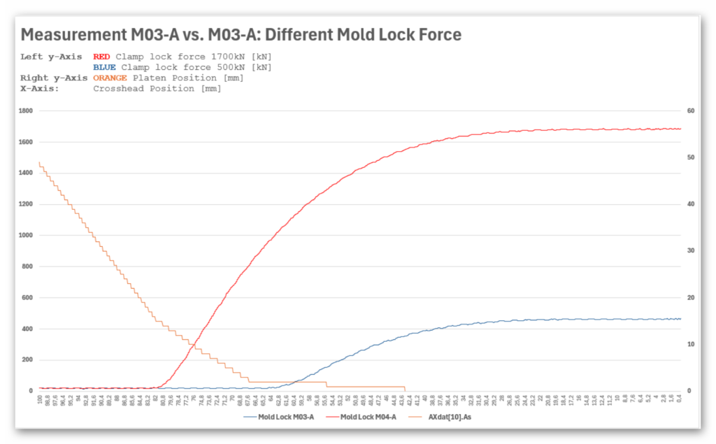
- Force rise depends on the target mold lock force.
- At 500 kN, the mold lock force begins to rise at approximately 64 mm crosshead position.
- At 1700 kN, the force rise begins significantly earlier, around 80 mm.
The mechanical behavior of the toggle system is therefore highly reproducible.
Measurement M05-A was performed at a target clamping force of 1700 kN, with a coin intentionally placed inside the mold to simulate foreign material.
The diagram compares:
- M04-A (red): Normal closing at 1700 kN, no foreign object
- M05-A (blue): Closing at 1700 kN with coin trapped in the mold
The mold lock force is displayed as a function of the crosshead position [mm], allowing precise analysis of when the force rise begins.
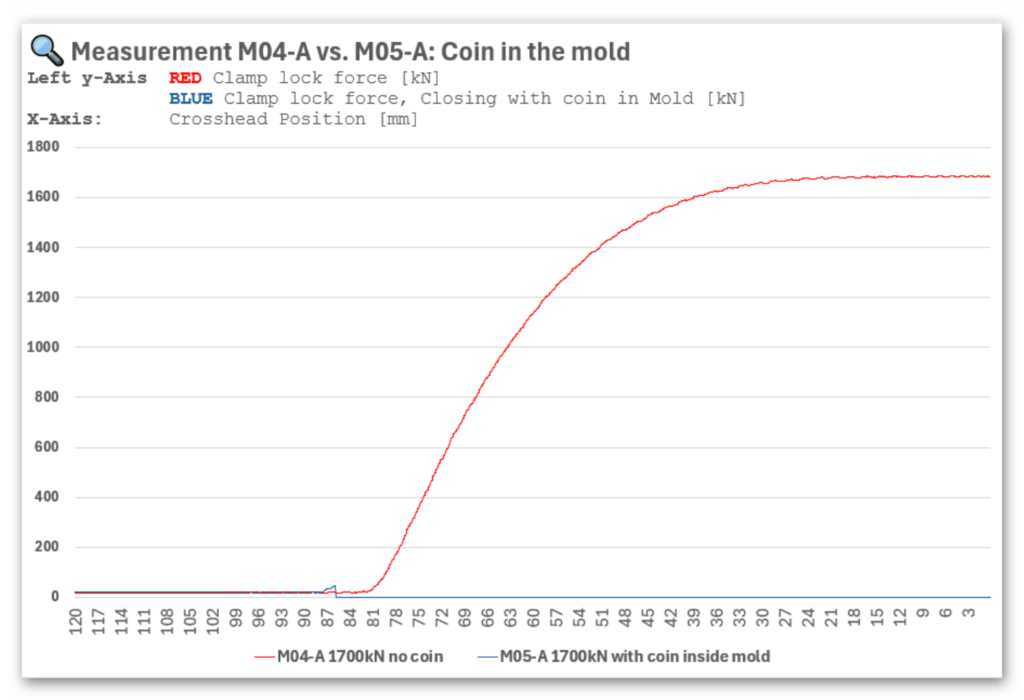
- In the normal cycle (M04-A, red), the mold lock force starts to rise around 80 mm crosshead position.
- With the coin inside the mold (M05-A, blue), the force increases much earlier, already before 84 mm, even though the absolute force is still very small at that point.
- The system detects this premature force rise and immediately aborts the Tonnage Build-Up phase.
- Because the abort happens early—long before the high-force region of the toggle is reached—the machine prevents any overshoot of the mold lock force.
- The early force deviation caused by the foreign object is highly reproducible and extremely precisely detectable.
- Monitoring the mold lock force relative to the crosshead position allows fast and reliable detection of foreign material in the mold.
- The early abort of Tonnage Build-Up prevents any overshoot of the configured clamping force, protecting the mold and the clamp unit from damage.
Measurement M05-A confirms that the proposed monitoring strategy—evaluating the force-rise point against the crosshead reference—provides a robust and precise safety mechanism.
Even small obstructions, such as a coin, cause a detectable shift in the force onset and are safely handled through an immediate abort of the tonnage build-up.
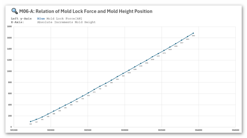
Measurement M06 investigates how the mold lock force changes when the mold height is shifted in defined increments.
The goal is to understand:
- whether the relation between mold height and resulting mold lock force is linear,
- whether this linearity can be used to calculate mold height automatically for any target clamping force,
- whether this linearity is valid for different mold types, with different stiffness and spring characteristics.
In this test, the mold height was increased step-by-step in 75 incremental steps, and the resulting mold lock forces were measured.
Findings
- The force–height relationship forms an almost perfect linear curve.
- This suggests that, for this specific mold and machine, mold height can be calculated directly and accurately from the target mold lock force.
- Currently, the machine uses a lookup table with three calibration points recorded during the calibration process.
The linear trend observed here indicates that a dynamic computation could completely replace this lookup table.
Open Question / Limitation
However, the question remains whether this linear behavior holds for:
- different mold sizes,
- different mold stiffness values,
- molds with integrated springs, slides, ejector systems, etc.
Your assumption (correctly) is:
The linearity will not be the same for different molds, because each mold has a different structural stiffness and may exhibit non-linear mechanical behavior during compression.
Therefore, while the linear model works for this specific mold, it may not universally apply.
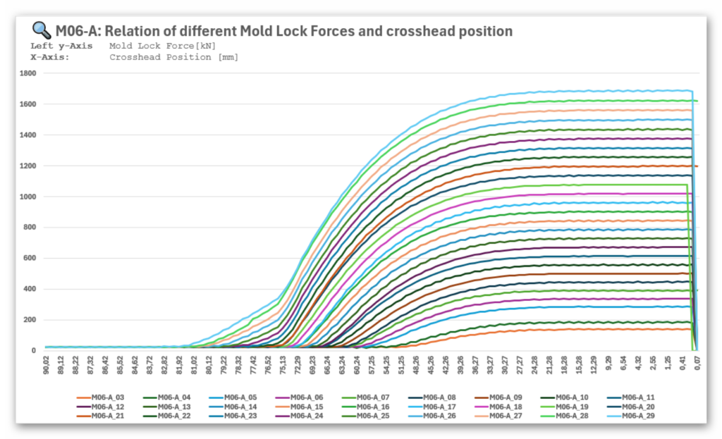
The second graphic shows 27 individual closing cycles, each with a different mold height setting.
The mold lock force is displayed relative to the crosshead position.
Findings
- All 27 curves follow the same characteristic toggle-behavior shape.
- As higher the set mold lock force is, as earlier the rise of mold lock force begins on the crosshead position axis.
Measurement M10 investigates how the clamp behaves when the Tonnage Build-Up phase is stopped in a controlled manner once the tie bar tension reaches 170 Nm.
The maximum mold lock force was configured to 1700 kN, but the process was intentionally halted earlier at the defined threshold value of 170 Nm, to evaluate mechanical behavior under different speeds.
Two scenarios were tested:
- M10-A_10 → Tonnage Build-Up speed = 10%
- M10-A_100 → Tonnage Build-Up speed = 100%
The plots show:
- Blue: Mold Lock Force [Nm] (tie bar tension sensor)
- Orange: Clamp Lock Speed [RPM]
- X-axis: Time [sec]
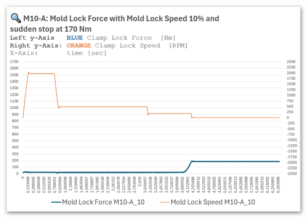
- At 10% speed, the force increases slowly and predictably.
- Once the force reaches the 170 Nm threshold, the control system initiates a smooth, controlled shutdown of the Tonnage Build-Up phase.
- Due to the low rotational speed and small mechanical inertia:
- The force overshoot is minimal.
- The resulting mold lock force stabilizes at approximately 200 Nm.
- The motor decelerates gently, with no oscillations or back-driving effects.
Conclusion
At low Tonnage Build-Up speed, the controlled shutdown is highly effective:
- Very low force overshoot
- No mechanical stress
- Clean and stable stop behavior
This represents the optimal operating condition for threshold-based protection.
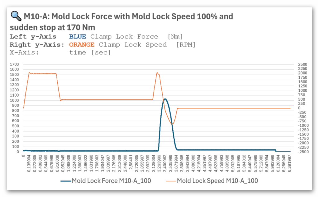
- At 100% speed, the clamp drive operates at a high RPM when entering the force-building region.
- As soon as the 170 Nm threshold value is exceeded, the system triggers a controlled shutdown of control step Tonnage Build-Up.
- However, because of the high inertia of the drivetrain:
- A large force peak occurs, reaching approximately 1050 Nm before the system decelerates fully.
- The abrupt braking causes a short reverse rotation of the servo motor.
This results in a brief force drop of around 50 Nm.
Conclusion
At high mold lock speeds, the controlled shutdown still operates correctly, but mechanical inertia causes:
- A substantial force overshoot
- A short rebound effect
vidalista 20 pills
vidalista 20 pills
sildenafil pills cvs
sildenafil pills cvs
cenforce 200mg dosage
cenforce 200mg dosage
cialis online buy
cialis online buy
vidalista reddit
vidalista reddit
cenforce viagra review
cenforce viagra review
cyclosporine psoriasis dosage
cyclosporine psoriasis dosage
buy stendra avanafil
buy stendra avanafil
semaglutide dosing schedule in units
semaglutide dosing schedule in units
semaglutide effetti collaterali vista
semaglutide effetti collaterali vista
köpa semaglutid tabletter sverige
köpa semaglutid tabletter sverige
semaglutid tablet
semaglutid tablet
doxycycline hyclate and alcohol
doxycycline hyclate and alcohol
bupropion smoking cessation and depression
bupropion smoking cessation and depression
acyclovir cream 5g
acyclovir cream 5g
liraglutide come with pen needles
liraglutide come with pen needles
ketoconazole complete overview
ketoconazole complete overview
ketoconazole cream complete guide
ketoconazole cream complete guide
ivermectin research summary
ivermectin research summary
ivermectin kinetic research
ivermectin kinetic research
minoxidil help & answers
minoxidil help & answers
avanafil absolute contraindications
avanafil absolute contraindications
vardenafil health contraindications
vardenafil health contraindications
avanafil online safety essentials
avanafil online safety essentials