


General
The Code Box allows the creation and configuration of up to four individual programs.
Each program defines logical conditions that control specific outputs.
The function must be enabled via the option page.

Program Structure
Each program consists of:
- 4 AND conditions
- Each condition may include an optional OR condition
Note:
- The first input block and the output block are always present and cannot be removed.
- Additional blocks can be added or removed using the Add and Delete (drag & drop) functions.
- If the first block or the output block is deleted or reset, its configuration is automatically restored to the default settings.
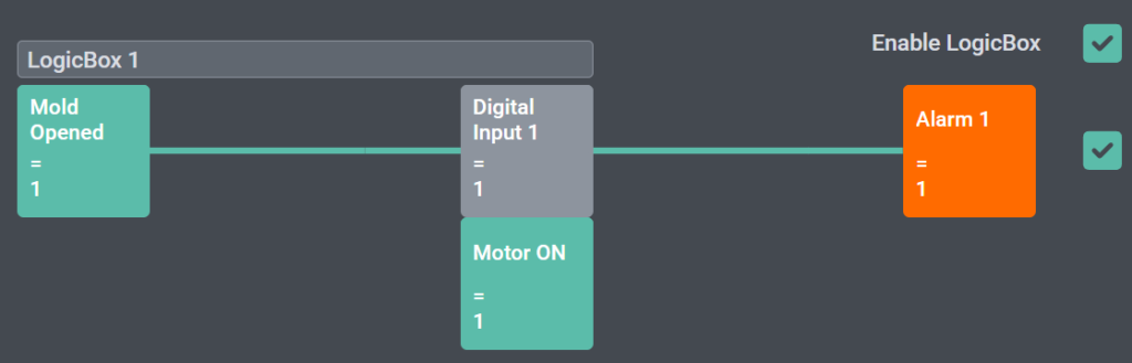
Visual Status Indication
The Code Box provides a visual representation of the program state:
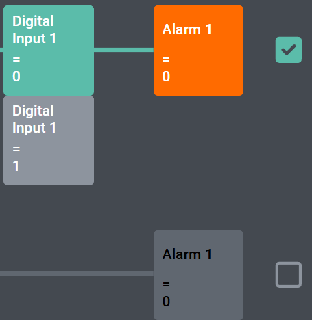
- Blocks change color depending on their status:
- Disabled
- Enabled
- Active
- A connecting line between the blocks indicates the logical chain:
- The line color reflects up to which point all conditions are fulfilled
- This allows a clear visual indication of where the logical chain is interrupted
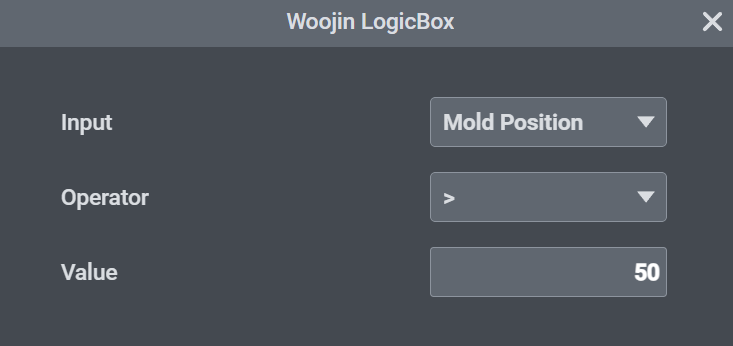
Block Configuration
Each block can be configured individually.
By clicking on a block, a configuration dialog opens where all relevant parameters can be adjusted.
Available settings include the selection of conditions, logical connections, and output definitions for the respective block.
Conditions
Conditions can be selected from various system signals, including:
- Digital inputs
- Mold close
- Mold position
- Core 1 IN END
- Injection pressure
- Ejector position
- Carriage forward
- Motor or heating ON
- Operating modes
- and further system signals
Each condition is defined by:
- a signal (condition source)
- a comparison operator (=, !=, <, <=, >, >=)
- a comparison value
The condition becomes true when the selected signal fulfills the defined comparison.
Outputs
Each program can control the following outputs:
- Alarms
- Digital Outputs
- Interlocks (Ejector, Injection, Mold)
- Motor Off
- Heating Off
Program Management
Each program can be assigned an individual name.
Program names and configurations are warm-start protected.
Programs can be:
- Disabled globally using a enable checkbox
- Enabled or disabled individually via checkboxes
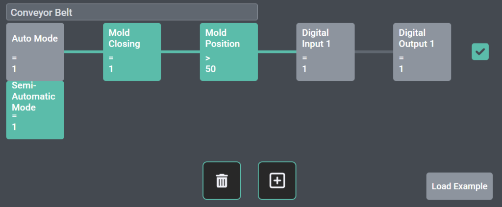
Example Program
An example configuration (e.g. a conveyor belt program) can be loaded:
- Press the “Load Example” button
- Confirm the action
- Program 4 will be overwritten and deleted
Hello,
We would like to clarify the following points regarding the LogicBox function.
1. I/O Assignment
2. Option Page Configuration (HMI)
3. Scope of HQ Responsibility
From HQ perspective, we understand the following:
Please confirm if this understanding is correct.
4. Additional Request
We need this clarification to ensure proper application and avoid misuse in the field.
Please provide your feedback.
Best regards,
Seunghyun Lee
Yes, pre-defined “user programmable logic-box signals” will be used. similar to “codebox” signal. Standard can be 2 logic-box inputs, and 2 logic-box outputs.
tadalafil tablet pronunciation
tadalafil tablet pronunciation
online cialis australia
online cialis australia
vidalista 20mg india
vidalista 20mg india
orlistat reviews
orlistat reviews
rogaine target nearby
rogaine target nearby
flagyl and breastfeeding safety
flagyl and breastfeeding safety
metronidazole topical cream 0.75 rosacea
metronidazole topical cream 0.75 rosacea
acyclovir walmart price
acyclovir walmart price
terbinafine dosage breakdown
terbinafine dosage breakdown
ketoconazole shampoo comparison
ketoconazole shampoo comparison
minoxidil men’s frontal hairline guide
minoxidil men’s frontal hairline guide
minoxidil pk insights
minoxidil pk insights
avanafil price overview page
avanafil price overview page