


1. Machine Option

2. User Settings (Injection / Cavity Pressure Settings page)
2.1 Cavity Pressure Settings
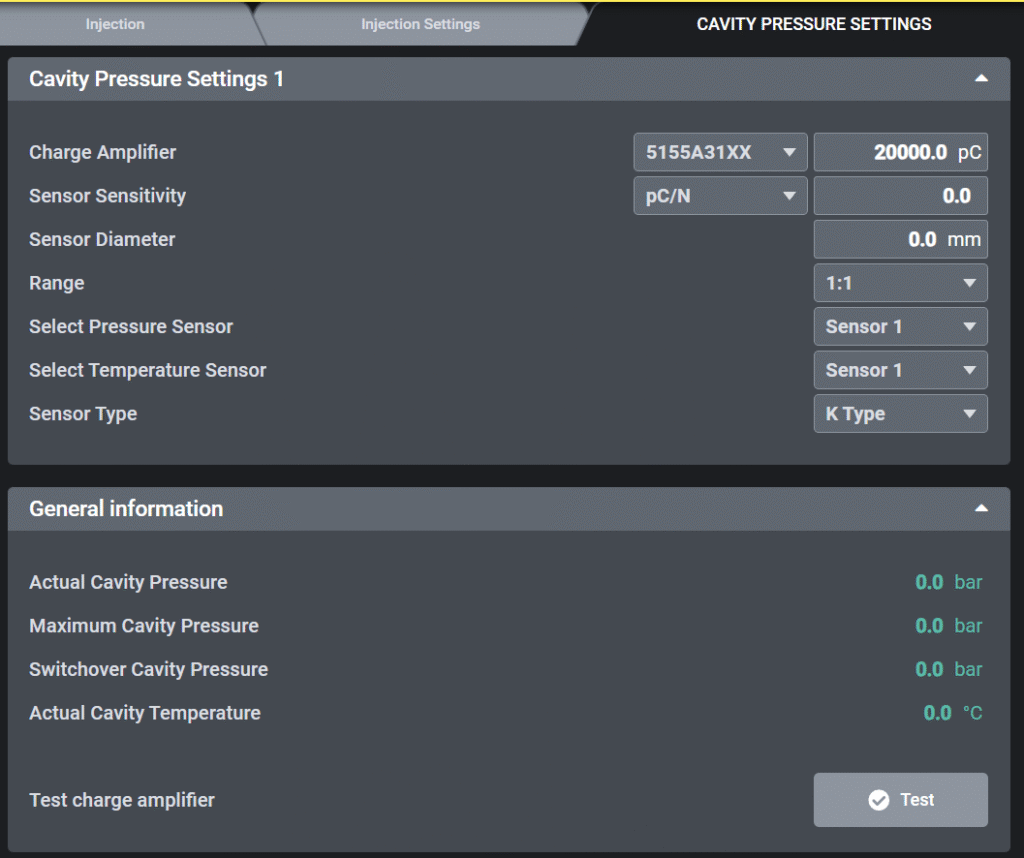
2.1.1 Cavity Pressure Settings 1
- Charge Amplifier
- Select the installed amplifier model (e.g., 5155A31XX, 5159A).
- Enter the maximum input charge range (e.g., 20,000 pC).
- Sensor Sensitivity
- Input the sensitivity value from the Kistler sensor datasheet (unit: pC/N or pC/bar).
- This ensures the correct conversion from charge to pressure.
- Sensor Diameter
- Enter the diaphragm size of the installed sensor (e.g., 4.0 mm, 6.0 mm, 8.0 mm).
- Range (Scaling)
- Defines how the measured value is scaled.
- Default: 1:1 (recommended, displays the measured value directly).
- Select Pressure Sensor
- Assign the pressure sensor channel to be used (e.g., Sensor 1).
- Select Temperature Sensor
- Assign the temperature sensor channel (e.g., Sensor 1).
- Sensor Type
- Select the thermocouple type used for temperature measurement.
- Default: K Type, other options (J, L, N) available if required.
2.1.2 General Information
- Actual Cavity Pressure
- Displays real-time cavity pressure (bar).
- Maximum Cavity Pressure
- Displays the peak cavity pressure reached during the cycle (bar).
- Switchover Cavity Pressure
- Displays the cavity pressure at the point of switchover (bar).
- Actual Cavity Temperature
- Displays the current cavity temperature measured by the sensor (°C).
- Test button
- The Test button is used to check the wiring and functionality of the Kistler amplifier and sensor.
- The button is not available in Auto mode or Semi-auto mode.
- Output signal:
- When the Test button is pressed, the system generates the digital output gDO.CavityTest.
- This signal is sent to the Kistler module, which activates the internal test function of the amplifier.
2.2 Switchover condition settings
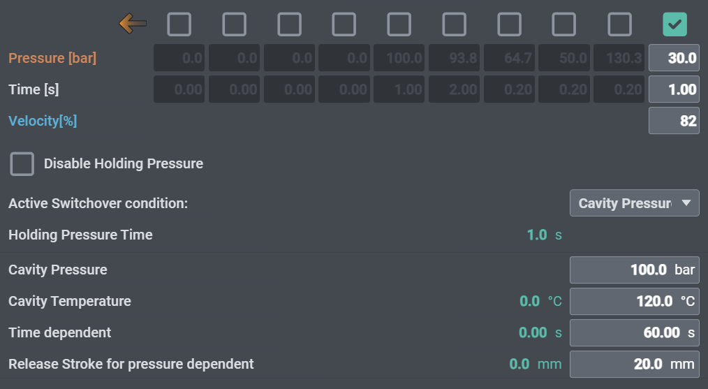
To use cavity pressure and temperature from the Kistler module as the switchover condition during injection:
- Set Active Switchover Condition to Cavity Pressure.
- Enter the Cavity Pressure and Cavity Temperature values to be used for switchover.
- Set the Time dependent parameter as a timeout to prevent process errors.
- Define the injection position where pressure switchover detection begins with Release Stroke for pressure dependent.
3. Kistler Datasheet
Datasheet link (Type 5159A)
https://kistler.cdn.celum.cloud/SAPCommerce_Download_original/003-468e.pdf
Datasheet link (Type 5155A)
https://kistler.cdn.celum.cloud/SAPCommerce_Download_original/000-403e.pdf